LABTECH KOREA

LABTECH VERIFIED ENGINEERING SOLUTION

Photodiode Measurement

Ultra-low current measurement for photodiodes

TECHNICAL GUIDE

Understanding Photodiode Measurement

1. Measurement Overview

A photodiode converts incident optical power into a small electrical current. Because the current can range from amperes down to picoamperes or below, the measurement circuit must provide sufficient gain while controlling noise, bandwidth and saturation.

2. Photodiode Operating Principle

Photons absorbed in the semiconductor generate electron-hole pairs. The internal electric field separates these carriers and produces photocurrent. The resulting current is approximately proportional to incident optical power within the linear operating range.

3. Equivalent Circuit

A practical photodiode can be represented by a photocurrent source in parallel with junction capacitance, shunt resistance and dark-current components. Junction capacitance and cable capacitance directly affect transimpedance-amplifier stability and achievable bandwidth.

4. Photovoltaic and Photoconductive Modes

Photovoltaic mode operates near zero external bias and generally favors low dark current and precision. Photoconductive mode applies reverse bias, reducing junction capacitance and improving response speed, but typically increases dark current and associated shot noise.

5. Why Use a Transimpedance Amplifier?

A transimpedance amplifier converts photocurrent into voltage while maintaining the photodiode input node near a controlled potential. The basic relationship is output voltage equals photocurrent multiplied by transimpedance gain, with polarity determined by the circuit connection.

6. Gain Selection

Choose the highest gain that does not saturate the amplifier during the largest expected photocurrent. The available output-voltage range, DC offsets, dark current and background-light current must all be included in the calculation.

7. Noise Considerations

Important noise sources include photodiode shot noise, dark-current shot noise, amplifier input-current noise, amplifier input-voltage noise, resistor thermal noise and environmental interference. Total integrated noise also increases with measurement bandwidth.

8. Bandwidth and Stability

Higher transimpedance gain generally reduces available bandwidth. Photodiode and cable capacitance increase the amplifier noise gain and can cause ringing or oscillation. Proper feedback compensation and short, shielded connections are therefore essential.
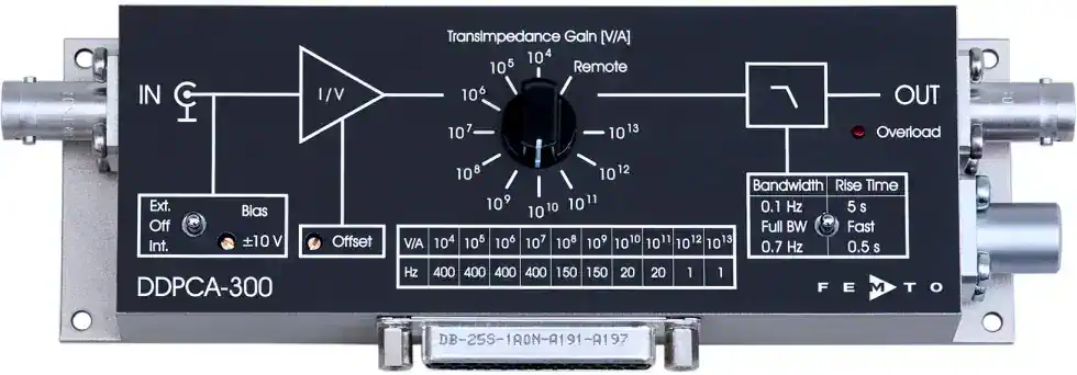
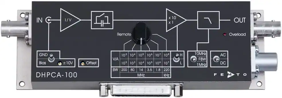
SYSTEM CONFIGURATION

Recommended Measurement Architecture

1Photodiode
2Short low-capacitance shielded cable
3Transimpedance or current amplifier
4Oscilloscope, data-acquisition system or lock-in amplifier
5Stable detector bias supply when photoconductive operation is required

SELECTION GUIDE

How to Select the Right Instrument

1

Estimate the minimum and maximum expected photocurrent.

2

Define the required measurement bandwidth or signal rise time.

3

Choose the gain from the desired output voltage and expected current.

4

Confirm that the selected gain supports the required bandwidth.

5

Check detector and cable capacitance against amplifier stability requirements.

6

Allow output headroom for dark current, offsets, background light and transient peaks.

7

Compare input-current noise and integrated output noise at the required bandwidth.

ENGINEERING NOTES

Practical Measurement Considerations

1

Use the shortest practical detector-to-amplifier input connection.

2

Avoid unnecessary adapters and long coaxial cables at the current input.

3

Keep detector bias and amplifier grounding arrangements free from ground loops.

4

Verify output polarity before interpreting the measured voltage.

5

High gain does not automatically provide the best measurement if bandwidth or saturation limits are exceeded.

6

Photodiode responsivity must be evaluated at the actual optical wavelength.

ENGINEERING CALCULATORS

Related Calculation Tools

Photodiode Current Calculator

Estimate photocurrent from incident optical power and detector responsivity.

Open Calculator

Transimpedance Gain Calculator

Calculate expected output voltage from detector current and amplifier gain.

Open Calculator

FREQUENTLY ASKED QUESTIONS

Engineering FAQ

How do I choose the correct transimpedance gain?

Divide the desired output-voltage magnitude by the expected photocurrent. Then verify that the amplifier supports the required bandwidth at that gain and that the largest possible current will not saturate the output.

Why does photodiode capacitance reduce bandwidth?

Photodiode and cable capacitance interact with the amplifier input and feedback network. This increases noise gain and can reduce bandwidth, cause peaking or create instability.

Should the photodiode be reverse biased?

Reverse bias can reduce junction capacitance and improve speed, but it generally increases dark current and shot noise. Zero-bias operation is often preferred for precision low-current measurements.

Why is the measured signal noisy at high gain?

High gain amplifies detector current, dark current, amplifier noise, leakage and environmental interference. Noise also rises as the effective measurement bandwidth increases.

BASIC CALCULATION

Photodiode Current Calculation

Photodiode current can be estimated from the incident optical power and the detector responsivity at the measurement wavelength.

Iphoto = Popt × Responsivity

Example: 10 µW of optical power with a responsivity of 0.5 A/W produces approximately 5 µA of photocurrent.

PRODUCT SELECTION

Recommended Products

VERIFIED SOURCES

Technical References

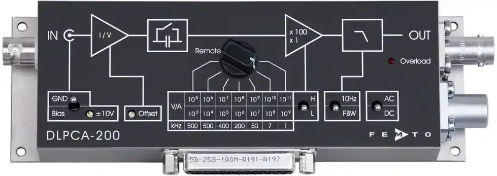
FEMTODLPCA-200 Variable-Gain Low-Noise Current AmplifierHamamatsu PhotonicsTechnical Note: Si PhotodiodesTexas InstrumentsDesigning Photodiode Amplifier CircuitsAnalog DevicesStabilize Your Transimpedance Amplifier